


Pulse Modulation
In Pulse modulation, a periodic sequence of rectangular pulses, is used as a carrier wave. This is further divided into analog and digital modulation.
In analog modulation technique, if the amplitude or duration or position of a pulse is varied in accordance with the instantaneous values of the baseband modulating signal, then such a technique is called as Pulse Amplitude Modulation (PAM) or Pulse Duration/Width Modulation (PDM/PWM), or Pulse Position Modulation (PPM).
In digital modulation, the modulation technique used is Pulse Code Modulation (PCM) where the analog signal is converted into digital form of 1s and 0s. As the resultant is a coded pulse train, this is called as PCM. This is further developed as Delta Modulation (DM). These digital modulation techniques are discussed in our Digital Communications tutorial
Amplitude Modulation
A continuous-wave goes on continuously without any intervals and it is the baseband message signal, which contains the information. This wave has to be modulated.
According to the standard definition, “The amplitude of the carrier signal varies in accordance with the instantaneous amplitude of the modulating signal.” Which means, the amplitude of the carrier signal containing no information varies as per the amplitude of the signal containing information, at each instant. This can be well explained by the following figures.
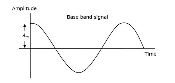
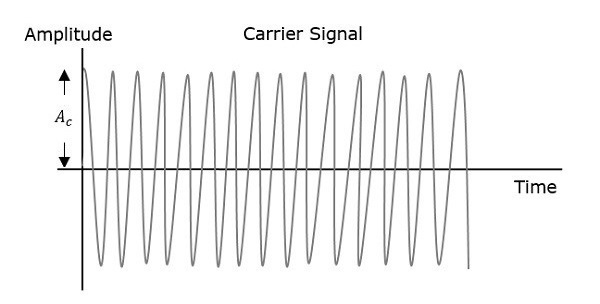

The first figure shows the modulating wave, which is the message signal. The next one is the carrier wave, which is a high frequency signal and contains no information. While, the last one is the resultant modulated wave.
It can be observed that the positive and negative peaks of the carrier wave, are interconnected with an imaginary line. This line helps recreating the exact shape of the modulating signal. This imaginary line on the carrier wave is called as Envelope. It is the same as that of the message signal.


