


Mutual Inductance
As the current carrying coil produces some magnetic field around it, if another coil is brought near this coil, such that it is in the magnetic flux region of the primary, then the varying magnetic flux induces an EMF in the second coil. If this first coil is called as Primary coil, the second one can be called as a Secondary coil.
When the EMF is induced in the secondary coil due to the varying magnetic field of the primary coil, then such phenomenon is called as the Mutual Inductance.
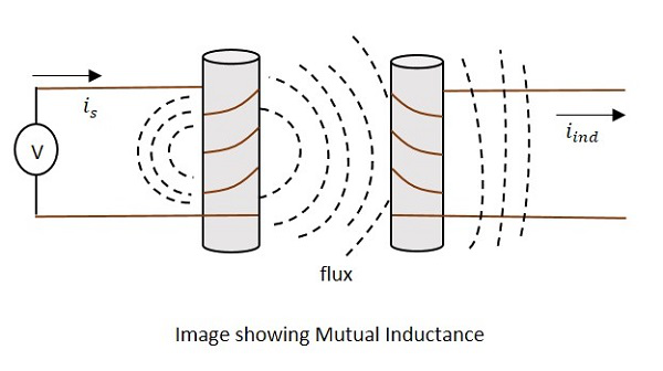
The current is in the figure indicate the source current while iind indicates the induced current. The flux represents the magnetic flux created around the coil. This spreads to the secondary coil also.
With the application of voltage, the current is flows and flux gets created. When the current is varies, the flux gets varied producing iind in the secondary coil, due to the Mutual inductance property.
The change took place like this.
Where,
- Vp ip Indicate the Voltage and current in Primary coil respectively
- B Indicates Magnetic flux
- Vs is Indicate the Voltage and current in Secondary coil respectively
Mutual inductance M of the two circuits describes the amount of the voltage in the secondary induced by the changes in the current of the primary.
Where the rate of change of current with time and M is the co-efficient of Mutual inductance. The minus sign indicates the direction of current being opposite to the source.
Units −
The units of Mutual inductance is
(From the above equation)
Depending upon the number of turns of the primary and the secondary coils, the magnetic flux linkage and the amount of induced EMF varies. The number of turns in primary is denoted by N1 and secondary by N2. The co-efficient of coupling is the term that specifies the mutual inductance of the two coils.
Factors affecting Inductance
There are a few factors that affect the performance of an inductor. The major ones are discussed below.
Length of the coil
The length of the inductor coil is inversely proportional to the inductance of the coil. If the length of the coil is more, the inductance offered by that inductor gets less and vice versa.
Cross sectional area of the coil
The cross sectional area of the coil is directly proportional to the inductance of the coil. The higher the area of the coil, the higher the inductance will be.
Number of turns
With the number of turns, the coil affects the inductance directly. The value of inductance gets square to the number of turns the coil has. Hence the higher the number of turns, square of it will be the value of inductance of the coil.
Permeability of the core
The permeability (μ) of the core material of inductor indicates the support the core provides for the formation of a magnetic field within itself. The higher the permeability of the core material, the higher will be the inductance.
Coefficient of Coupling
This is an important factor to be known for calculating Mutual inductance of two coils. Let us consider two nearby coils of N1 and N2 turns respectively.
The current through first coil i1 produces some flux Ψ1. The amount of magnetic flux linkages is understood by weber-turns.
Let the amount of magnetic flux linkage to the second coil, due to unit current of i1 be
This can be understood as the Co-efficient of Mutual inductance, which means
Hence the Co-efficient of Mutual inductance between two coils or circuits is understood as the weber-turns in one coil due to 1A of current in the other coil.
If the self-inductance of first coil is L1, then
Similarly, coefficient of mutual inductance due to current i2 in the second coil is
If self-inductance of second coil is L2
Therefore,
Multiplying 1 and 2, we get
The above equation holds true when the whole changing flux of primary coil links with the secondary coil, which is an ideal case. But in practice, it is not the case. Hence, we can write as
Where K is known as the coefficient of coupling.
The Coefficient of coupling K can be defined as the ratio of actual coefficient of mutual inductance to the ideal (maximum) coefficient of mutual inductance.
If the value of k is near to unity, then the coils are said to be tightly coupled and if the value of k = 0, then the coils are said to be loosely coupled.
Applications of Inductors
There are many applications of Inductors, such as −
- Inductors are used in filter circuits to sense high-frequency components and suppress noise signals
- To isolate the circuit from unwanted HF signals.
- Inductors are used in electrical circuits to form a transformer and isolate the circuits from spikes.
- Inductors are also used in motors.
Circuit Connections in Inductors
An Inductor when connected in a circuit, that connection can be either series or parallel. Let us now know what will happen to the total current, voltage and resistance values if they are connected in series as well, when connected in parallel.
Inductors in Series
Let us observe what happens, when few inductors are connected in Series. Let us consider three resistors with different values, as shown in the figure below.
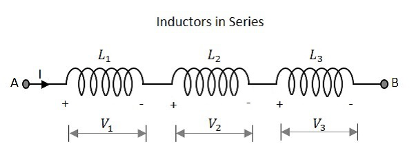
Inductance
The total inductance of a circuit having series inductors is equal to the sum of the individual inductances. Total inductance value of the network given above is
Where L1 is the inductance of 1st resistor, L2 is the inductance of 2nd resistor and L3 is the inductance of 3rd resistor in the above network.
Voltage
The total voltage that appears across a series inductors network is the addition of voltage drops at each individual inductances.
Total voltage that appears across the circuit
Where V1 is the voltage drop across 1st inductor, V2 is the voltage drop across 2nd inductor and V3 is the voltage drop across 3rd inductor in the above network.
Current
The total amount of Current that flows through a set of inductors connected in series is the same at all the points throughout the network.
The Current through the network
Where I1 is the current through the 1st inductor, I2 is the current through the 2nd inductor and I3 is the current through the 3rd inductor in the above network.
Inductors in Parallel
Let us observe what happens, when few resistors are connected in Parallel. Let us consider three resistors with different values, as shown in the figure below.
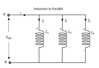
Inductance
The total inductance of a circuit having Parallel resistors is calculated differently from the series inductor network method. Here, the reciprocal (1/R) value of individual inductances are added with the inverse of algebraic sum to get the total inductance value.
Total inductance value of the network is
Where L1 is the inductance of 1st inductor, L2 is the inductance of 2nd inductor and L3 is the inductance of 3rd inductor in the above network.
From the method we have for calculating parallel inductance, we can derive a simple equation for two-inductor parallel network. It is
Voltage
The total voltage that appears across a Parallel inductors network is same as the voltage drops at each individual inductances.
The Voltage that appears across the circuit
Where V1 is the voltage drop across 1st inductor, V2 is the voltage drop across 2nd inductor and V3 is the voltage drop across 3rd inductor in the above network. Hence the voltage is same at all the points of a parallel inductor network.
Current
The total amount of current entering a Parallel inductive network is the sum of all individual currents flowing in all the Parallel branches. The inductance value of each branch determines the value of current that flows through it.
The total Current through the network is
Where I1 is the current through the 1st inductor, I2 is the current through the 2nd inductor and I3 is the current through the 3rd inductor in the above network.
Hence the sum of individual currents in different branches obtain the total current in a parallel network.
Inductive Reactance
Inductive Reactance is the opposition offered by an inductor to the alternating current flow, or simply AC current. An inductor has the property of resisting the change in the flow of current and hence it shows some opposition which can be termed as reactance, as the frequency of the input current should also be considered along with the resistance it offers.
- Indication − XL
- Units − Ohms
- Symbol − Ω
In a purely inductive circuit, the current IL lags the applied voltage by 90°. Inductive reactance is calculated by,
Where f is the frequency of the signal. Hence inductive reactance is a function of frequency and inductance.
Basic Electronics - Types of Inductors
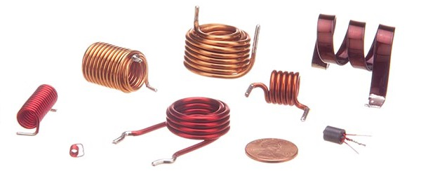
Inductors are available in different shapes and has different uses. Their sizes vary depending upon the material used to manufacture them. The main classification is done as fixed and variable inductors. An inductor of few Henries may be in a dumbbell shape at the size of a simple resistor. A fixed inductor always has silver as its first color in color coding.
The Core of the Inductor is its heart. There are many types of Inductors according to the core material used. Let us have a look at a few of them.
Air-core Inductor
The commonly seen inductor, with a simple winding is this air-Core Inductor. This has nothing but air as the core material. The non-magnetic materials like plastic and ceramic are also used as core materials and they also come under this air-core Inductors. The following image shows various air-core inductors.
These Inductors offer a minimum signal loss at the applications having a very high magnetic field strength. Also, there exists no core losses as there is no solid core material.
Iron-Core Inductor
These Inductors have Ferromagnetic materials, such as ferrite or iron, as the core material. The usage of such core materials helps in the increase of inductance, due to their high magnetic permeability. Permeability measures the ability of supporting the formation of magnetic fields within the materials. The following image shows how an Iron-core Inductor looks like −
The inductors that have ferromagnetic core materials just like these, suffer from core losses and energy losses at high frequencies. These Inductors are used in the manufacture of few types of transformers.
Toroidal Inductors
These Inductors have a magnetic material as the core substance to which the wire is wound. These are in circular ring shape, just as shown in the following figure.
The main advantage of this type of inductors is that, due to the circular shape, symmetry is achieved in the whole shape of the inductor, due to which there are minimum losses in the magnetic flux. These inductors are mostly used in AC circuit applications.
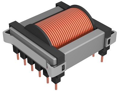
Laminated Core Inductors
These are the inductors that have laminated thin steel sheets, such as stacks, as the core materials. Usually for an inductor, if the loop area is increased for the current to travel, the energy losses will be more. Whereas, in these laminated core Inductors, thin steel sheets of stacks are helpful in blocking the eddy currents, which minimize the loop action.
The following figure shows an image of a laminated core inductor.
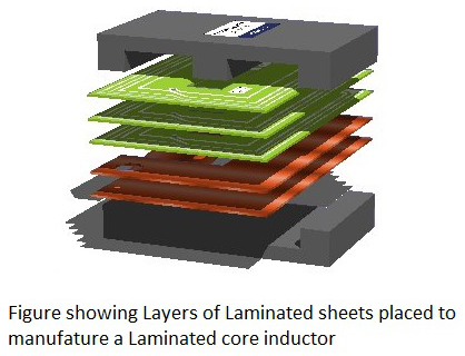
The main advantage of these inductors is minimizing the energy loss with its construction. These laminated core inductors are mostly used in the manufacture of transformers.
Powdered Iron Core Inductors
As the name implies, the core of these inductors have magnetic materials with some air gaps in it. But this kind of construction provides an advantage to the core, to store high level of energy compared with the other types. The following figure shows an image of a Powdered Iron core Inductor.
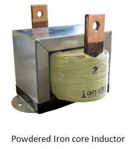
These inductors provide very low eddy current losses and hysteresis losses. These are available at lowest prices and have very good inductance stability.
Basic Electronics - RF Inductors
RF inductors are the radio frequency inductors, which are used at high resonant frequencies. These can be multilayered coil inductor or a thin film coated ceramic inductor or some wire wound ceramic inductor. The following figure represents few RF inductors.
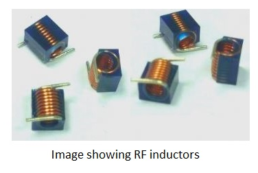
These inductors are characterized by low current rating and high electrical resistance. But as the high frequencies are used here, the wire resistance increases. Also, few effects come into picture because of these high resonant radio frequencies. Let us have a look at them.
Skin Effect
At high frequencies, the alternating current has a tendency of unequal distribution of current through the conductor. The electric current flows highly at the surface of the conductor than at its center. It gets its energy concentrated in the skin of the conductor, leaving the deep core of the conductor, as shown in the following figure.
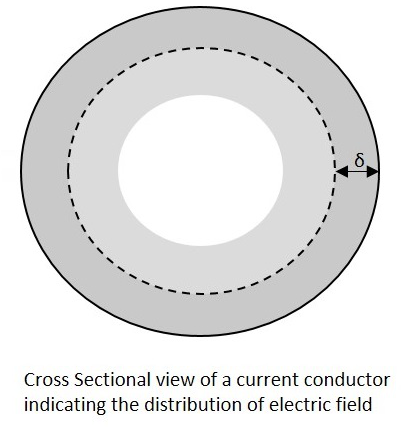
As the energy gets concentrated at the skin of the conductor, this effect is called as the Skin Effect. Actually this skin effect is caused due to the eddy currents which are produced by the changing Magnetic field, resulting from alternating current. Now-a-days, the conductors carrying higher frequencies are made in the form of tube shape, in order to reduce the weight and cost of the conductors.
Proximity Effect
Along with the above one, this is another effect, which is observed here. Proximity effect is the one which increases the resistance of the wire at high frequencies. Proximity is the word which says that the effect will be on adjacent wires. The following figure shows the concentration of current on the edges of the adjacent cables.
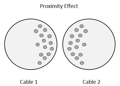
Each turn has some magnetic field which induces eddy currents in the wire that causes the current to be focused on the side of the adjacent wire. With this effect, the effective cross sectional area of the wire gets reduced and its resistance gets increased.
Parasitic Capacitance
Usually, an inductor internally contains a resistor in series (wire resistance) and a capacitor in shunt (parasitic capacitance). Each turn of winding has slightly different potential, in an inductor. The following figure shows the capacitance effect in an inductor.
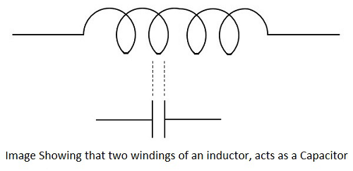
The two conductors that present in each turn, act as capacitor plates with air as dielectric. A capacitance called as Parasitic Capacitance exists here. In order to avoid this in certain applications, the windings are made far to each other.
As the frequency increases, the impedance of the parasitic capacitance decreases and the impedance of inductor increases. Hence the inductor tends to behave like a capacitor.
Dielectric losses
The current through the conductor of an inductor makes the molecules of the insulators exert energy in the form of heat. The higher the frequency, the greater the heat dissipation will be.
Chokes
Inductors are also called as chokes. An Inductor blocks AC components and sends DC components through it. Hence as it chokes or stops AC, an inductor can simply be termed as a Choke.
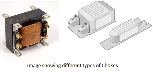
A coil of insulated wire is often wound on a magnetic core to form a choke. As the signal frequency increases, the impedance of the choke increases. Due to its reactance, it can limit the amount AC through it. Even though, practically some amount of AC passes through it due to its low electrical resistance. These are mostly used in tube lights and in transformers in electronic applications.
Basic Electronics - Transformers
According to the principle of Electromagnetic Induction, we have already learnt that, a varying flux can induce an EMF in a coil. By the principle of Mutual induction, when another coil is brought beside such coil, the flux induces EMF into the second coil.
Now, the coil which has the varying flux is called as the Primary Coil and the coil into which EMF is induced is called as the Secondary Coil, while the two coils together makes a unit called as a Transformer.
Transformer
A transformer has a primary coil to which input is given and a secondary coil from which the output is collected. Both of these coils are wound on a core material. Usually an insulator forms the Core of the transformer.
The following figure shows a practical transformer.
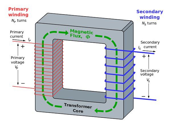
From the above figure, it is evident that few notations are common. Let us try to have a note of them. They are −
- Np = Number of turns in the primary winding
- Ns = Number of turns in the secondary winding
- Ip = Current flowing in the primary of the transformer
- Is = Current flowing in the secondary of the transformer
- Vp = Voltage across the primary of the transformer
- Vs = Voltage across the secondary of the transformer
- Φ = Magnetic flux present around the core of the transformer.
Transformer in a Circuit
The following figure shows how a transformer is represented in a circuit. The primary winding, the secondary winding and the core of the transformer are also represented in the following figure.
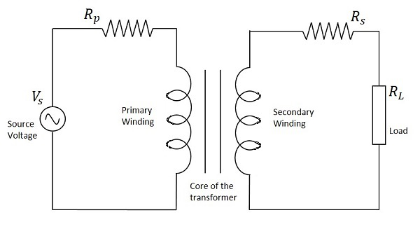
Hence, when a transformer is connected in a circuit, the input supply is given to the primary coil so that it produces varying magnetic flux with this power supply and that flux is induced into the secondary coil of the transformer, which produces the varying EMF of the varying flux. As the flux should be varying, for the transfer of EMF from primary to secondary, a transformer always works on alternating current AC.
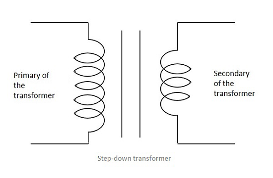
Step-up and Step-down
Depending upon the number of turns in the secondary winding, the transformer can be called as a Step up or a Step down transformer.
The main point to be noted here is that, there will not be any difference in the primary and secondary power of the transformer. Accordingly, if the voltage is high at secondary, then low current is drawn to make the power stable. As well, if the voltage in the secondary is low, then high current is drawn so as the power must be same as the primary side.
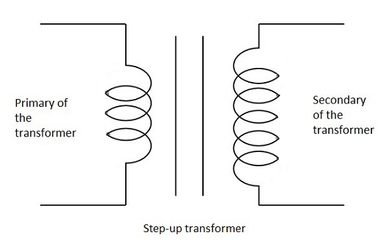
Step Up
When the secondary winding has more number of turns than the primary winding, then the transformer is said to be a Step-up transformer. Here the induced EMF is greater than the input signal.
Step Down
When the secondary winding has lesser number of turns than the primary winding, then the transformer is said to be a Step-down transformer. Here the induced EMF is lesser than the input signal.
Turns Ratio
As the number of turns of primary and secondary windings affect the voltage ratings, it is important to maintain a ratio between the turns so as to have an idea regarding the voltages induced.
The ratio of number of turns in the primary coil to the number of turns in the secondary coil is called as the “turns ratio” or “the ratio of transformation”. The turns ratio is usually denoted by N.
The ratio of the primary to the secondary, the ratio of the input to the output, and the turns ratio of any given transformer will be the same as its voltage ratio. Hence this can be written as
The turns ratio also states whether the transformer is a step-up or a step-down transformer. For example, a turns ratio of 1:3 states that the transformer is a step-up and the ratio 3:1 states that it is a step-down transformer.
Basic Electronics - Types of Transformers
Coming to the classification of transformers, there are many types depending upon the core used, windings used, place and type of usage, voltage levels etc.
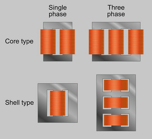
Single and three phase transformers
According to the supply used, the transformers are mainly classified as Single phase and three phase transformers.
- A normal transformer is a single phase transformer. It has a primary and a secondary winding and it is operated to either decrease or increase the secondary voltage.
- For a three phase transformer, three primary windings are connected together and three secondary windings are connected together.
A single three phase transformer is preferred to three single phase transformers so as to get good efficiency, where it occupies less space at low cost. But due to the transportation problem of heavy equipment, single phase transformers are used in most cases.
Another classification of these transformers is Core and Shell type.
- In Shell type, the windings are positioned on a single leg surrounded by the core.
- In Core type, they are wounded on different legs.
The difference is well known by having a look at the following figure.
The classification of transformers can also be done depending upon the type of core material used. These are actually RF transformers, which contain many types such as Air-core transformers, Ferrite core transformers, Transmission line transformers and Balun transformers. Balun transformers are used in RF receiver systems. The main types are the air core and iron core transformers.
Air-core Transformer
This is a core type transformer in which the windings are wound on a non-magnetic strip. The magnetic flux linkages are made through air as core between the primary and secondary. The following image shows an air-core transformer.
Advantages
- The hysteresis and eddy current losses are low in these Air core transformers.
- Noise production is low.
Disadvantages
- The reluctance is high in Air core transformers.
- Mutual inductance is low in Air core compared to Iron-core transformers.
Applications
- Audio frequency transformers.
- High frequency radio transmissions.
Iron Core Transformers
This is a core type transformer in which the windings are wound on an iron core. The magnetic flux linkages are made strong and perfect with iron as core material. This is commonly seen in laboratories. The figure below shows an example of iron core transformer.
Advantages
- They have very high magnetic permeability.
- Iron core transformers has low reluctance.
- Mutual Inductance is high.
- These transformers are highly efficient.
Disadvantages
- These are a bit noisy compared to Air core transformers.
- The hysteresis and eddy current losses are a bit more than Air core transformers.
Applications
- As isolation transformers.
- High frequency radio transmissions.
The transformers are also classified according to the type of core they use. Some transformers use the core immersed in oil. This oil is cooled from outside by various methods. Such transformers are named as Wet core transformers, while the others such as ferrite core transformers, laminated core transformers, toroidal core transformers and cast resin transformers are Dry core transformers.
Based on the type of winding technique, we have another transformer which is very popular named as the Auto transformer.
Auto Transformer
This is type of transformer which is mostly seen in our electrical laboratories. This auto transformer is an improved version of the original transformer. A single winding is taken to which both the sides are connected to power and the ground. Another variable tapping is made by whose movement secondary of the transformer is formed.
The following figure shows the circuit of an auto-transformer.
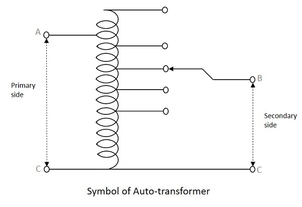
As shown in the figure, a single winding provides both primary and secondary in a transformer. Various tapping of secondary winding are drawn to select various voltage levels at the secondary side.
The primary winding as shown above is from A to C and the secondary winding is from B to C whereas the variable arm B is varied to get the required voltage levels. A practical auto transformer looks like the figure below.
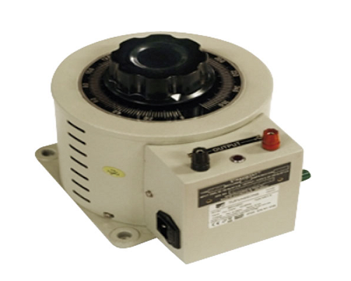
By rotating the shaft above, the secondary voltage is adjusted to different voltage levels. If the voltage applied across the points A and C is V1, then the voltage per turn in this winding will be
Now, the voltage across the points B and C will be
This constant is nothing but the turns ratio or voltage ratio of the auto transformer.
Transformers based on Usage
There are transformers which are classified depending upon the applications they have. Many of these transformers are large and bulky. Most of them are used by the Electricity department.
Power Transformers
The Power transformers are used in high power transfer applications for both step-up and step-down applications, where the operating voltages are more than 33KV generally rated above 200MVA. The flux density is much higher for them.
All the transformers that are used for power control applications such as laminated core transformers, toroidal transformers, variable auto transformers, polyphaser transformers, stray leakage transformers come under this category.
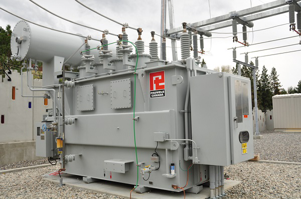
These are usually big in size depending upon the power handling capacity and its application. These transformers are available in three phase or single phase type. As these transformers are bulky, they are placed in large open area. These transformers tend to provide 100% efficiency in full load applications.
Advantages
- They have high insulation level.
- Noise is low.
- They are highly efficient.
- High voltage rated ones to handle high power applications.
Applications
- They are used in power generation systems.
- They are used in transmission sub stations.
Measurement Transformers
The Measurement transformers are used for measuring high voltage and high currents. These are mostly helpful in isolating the circuits from them. Usually, the Primary of a transformer is connected with high inputs of voltages and currents whereas Secondary of the transformer is connected to some relay or circuit which has to be provided some isolation.
These are mainly of two types, Current transformers and Voltage transformers. Let us have a look at each of them.
Current Transformer
The Current transformers provide current in the secondary circuit proportional to the current in the primary circuit. These are used in protective relays and for measurement purposes.
A single turn primary winding is passed through a well-insulated toroidal core transformer which is wounded with many turns, which makes a Current Transformer. This is always connected in series.
The secondary winding can be designed to provide single output or it may have several tapping for different values. Care must be taken that the secondary winding is connected to its load having low impedance, while current flows in primary. This is to avoid sudden high voltages in open circuited secondary which might permanently damage the accuracy of the transformer.
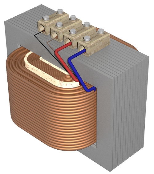
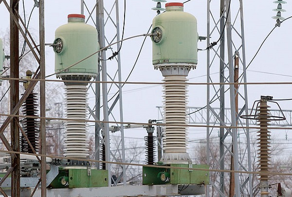
Voltage Transformers
The Voltage Transformers provide voltage in the secondary circuit proportional to the voltage in the primary circuit. These transformers are also called as Potential Transformers. These are connected in parallel to the circuit.
The primary of this transformer may have phase to phase connections but the secondary will have one terminal to ground. The figure below shows an image of a voltage transformer.
There are three main types of a voltage transformers. They are
- Electromagnetic − uses a wire wound transformer having good flux linkages.
- Capacitor − uses a capacitor with potential divider network.
- Optical − makes use of electrical properties of optical materials.
The voltage transformers are used in protective relays and for measurement purposes and also for phasor phase shift isolation.
Protection Transformers
These transformers are very accurate than measuring transformers, as these are used only to protect the circuits from high voltages and currents. The primary of these transformers are connected with high inputs whereas the secondary of the transformer keeps the circuit or relay, isolated from the sudden spikes or surges which might damage the circuit.
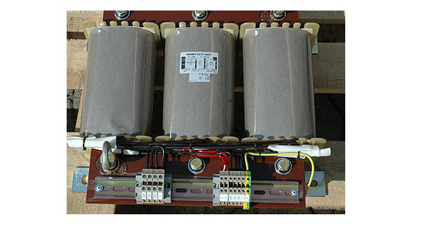
Distribution Transformers
The Distribution transformers are used for distribution of electrical energy at end-user level. The operating voltages are around 33KV for industrial purposes and 440v-220v for domestic purposes. These are generally rated below 200MVA.
The large three phase auto transformers used in power distribution and the oil-cooled transformers also come under this category. The figure below shows an image of a distribution transformer.
These transformers are usually smaller in size compared to power transformers. These transformers are placed in open but are not fully loaded like power transformers.
Advantages
- They are small in size.
- They are easy to install.
- These transformers have low magnetic losses.
Disadvantages
- These transformers have low efficiency.
- They are not fully-loaded.
Applications
They are used for distributing electricity in various areas like houses, farm yards, lands, railways, wind farms etc.
Basic Electronics - Transformer Efficiency
When the Primary of a transformer has some voltage induced, then the magnetic flux created in the primary is induced into the secondary due to mutual induction, which produces some voltage into the secondary. The strength of this magnetic field builds up as the current rises from zero to maximum value which is given by .
The magnetic lines of flux pass through the secondary winding. The number of turns in the secondary winding determines the voltage induced. Hence the amount of voltage induced will be determined by
Where N = number of turns in the secondary winding
The frequency of this induced voltage will be same as the frequency of primary voltage. The peak amplitude of the output voltage will be affected if the magnetic losses are high.
Induced EMF
Let us try to draw some relationship between induced EMF and number of turns in a coil.
Let us now assume that both the primary and the secondary coils has a single turn each. If one volt is applied to one turn of the primary with no losses (ideal case) the current flow and magnetic field generated induce the same one volt in the secondary. Hence voltage is same on both sides.
But the magnetic flux varies sinusoidally which means,
Then the basic relationship between induced EMF and coil winding of N turns is
Where
f = flux frequency in Hertz =
N = number of coil windings
∅ = flux density in webers
This is known as Transformer EMF Equation.
As alternating flux produces current in the secondary coil, and this alternating flux is produced by alternating voltage, we can say that only an alternating current AC can help a transformer work. Hence a transformer doesn’t work on DC.
Losses in Transformers
Any Device has few losses in practical applications. The main losses that occur in the transformers are Copper losses, Core losses and Flux leakage.
Copper Losses
Copper loss is the loss of energy, due to the heat produced by the current flow through the windings of the transformers. These are also called as “I2R losses” or “I squared R losses” as the energy lost per second increases with the square of the current through the winding and is proportional to the electrical resistance of the winding.
This can be written in an equation as
Where
- IP = Primary Current
- RP = Primary Resistance
- IS = Secondary Current
- RS = Secondary Resistance
Core Losses
Core Losses are also called as Iron Losses. These losses depends upon the core material used. They are of two types namely, Hysteresis and Eddy Current losses.
- Hysteresis Loss − The AC induced in the form of magnetic flux keeps on fluctuating (like rise and falls) and reversing the direction according to the AC voltage induced. Some energy is lost in the core due to these random fluctuations. Such loss can be termed as Hysteresis loss.
- Eddy Current Loss − While this whole process goes on, some currents are induced in the core which circulate continuously. These currents produce some loss called as Eddy Current Loss. Actually the varying magnetic field is supposed to induce current only in the secondary winding. But it induces voltages in the nearby conducting materials also, which results in this loss of energy.
- Flux Leakage − Though the flux linkages are strong enough to produce the required voltage, there will be some flux which gets leaked in practical applications and hence results in the energy loss. Though this is low, this loss is also countable when it comes to high energy applications.
Power of a Transformer
When an ideal transformer is considered with no losses, the Power of the transformer will be constant, as the product when voltage V multiplied by current I is constant.
We can say that the power in the primary equals the power in the secondary as the transformer takes care of that. If the transformer, steps-up the voltage then the current is reduced and if the voltage is stepped-down, the current is increased so as to maintain the output power constant.
Hence the primary power equals the secondary power.
Where ∅P = Primary phase angle and ∅S = Secondary phase angle.


