


The Capacitors whose value is fixed while manufacturing and cannot be altered later are called as Fixed Capacitors. The main classification of fixed capacitors is done as polarized and non-polarized. Let us have a look at Non-polarized capacitors.
Non-Polarized Capacitors
These are the capacitors that have no specific polarities, which means that they can be connected in a circuit, either way without bothering about the placement of right lead and left lead. These capacitors are also called as Non-Electrolytic Capacitors.
The main classification of Non-Polarized capacitors is done as shown in the following figure.
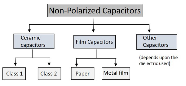
Among the types of capacitors, let us first go through the Ceramic Capacitors.
Ceramic Capacitors
The common capacitors used among fixed type are Ceramic Capacitors. The Ceramic capacitors are fixed capacitors that have ceramic material as a dielectric.
These ceramic capacitors are further classified as class1 and class2 depending upon their applications. For instance, Class1 has high stability and works best for resonant circuit applications, while class2 has high efficiency and gives its best for coupling applications.
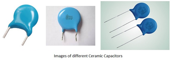
A hollow tubular or plate like ceramic material such as titanium dioxide and barium titanate is coated with a deposition of silver compound on both walls, so that both sides act as two capacitor plates and ceramic acts as a dielectric. Leads are drawn from these two surfaces and this whole assembly is encapsulated in a moisture-proof coating.
The most often used modern ceramic capacitors are Multi-Layer Chip Capacitors (MLCC). These capacitors are made in surface mounted technology and are mostly used due to their small size. These are available in the order of 1ηF to 100µF.
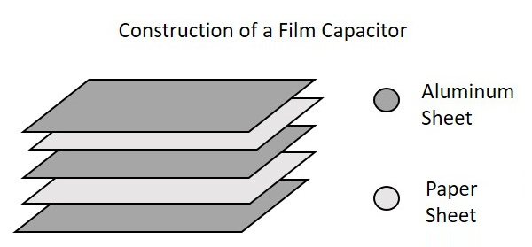
Film Capacitors
The Film Capacitors are the ones which have a film substance as a dielectric material. Depending upon the type of film used, these are classified as Paper and Metal film capacitors.
These film capacitors are both paper dielectric capacitors whereas a paper capacitor uses a waxed paper while a metallic film capacitor uses a metallized paper. The arrangement is almost same as shown below.
Paper Capacitors
Paper capacitors use Paper as a dielectric material. Two thin tin foil sheets are taken and placed between thin waxed or oiled paper sheets. This paper acts as a dielectric. Now-a-days paper is being replaced by plastic.
These sheets are sandwiched and are rolled into a cylindrical shape and encapsulated in a plastic enclosure. Leads are drawn out. The following figure shows an example of Paper Capacitors.
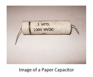
Paper capacitors are available in the order of 0.001µF to 2µF and the voltage rating can be as high as 2000volts. These capacitors are useful in high voltage and current applications.
Metal Film Capacitors
Metal Film capacitors are another type of film capacitors. These are also called as Metal Foil Capacitors or Metallized Paper Capacitors as the dielectric used here is a paper coated with metallic film.
Unlike in paper capacitors, a film of Aluminum or Zinc is coated on a paper to form a dielectric in this metallic film capacitors. Instead of Aluminum sheets placing between papers, the paper itself is directly coated here. This reduces the size of the capacitor.
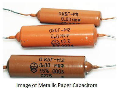
The Aluminum coating is preferred over zinc coating so as to avoid destruction of capacitor due to chemical reduction. The Aluminum coated sheets are rolled in the form of a cylinder and leads are taken. This whole thing is encapsulated with wax or plastic resin to protect the capacitor. These capacitors are useful in high voltage and current applications.
Other Capacitors
These are the miscellaneous capacitors that are named after the dielectric materials used. This group includes Mica Capacitors, Air Capacitors, Vacuum Capacitors and Glass Capacitors etc.
Mica Capacitors
The Mica Capacitors are made by using thin Mica sheets as dielectric materials. Just like paper capacitors, thin metal sheets are sandwiched with mica sheets in between. Finally the layers of metal sheets are connected at both ends and two leads are formed. Then the whole assembly is enclosed in plastic Bakelite capsule. The following image shows how a Mica capacitor looks like.
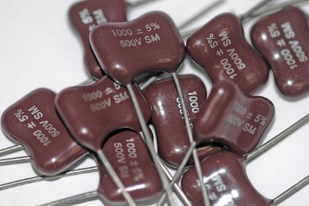
Mica Capacitors are available in the range of 50pF to 500pF. The Mica capacitors have high working voltage up to 500volts. These are most commonly used capacitors for electronic circuits such as ripple filters, Resonant circuits, Coupling circuits and high power, high current RF broadcast transmitters.
Air Capacitors
The Air Capacitors are the ones with air as dielectric. The simplest air capacitors are the ones with conducting plates having air in between. This construction is exactly the same as the variable tuning capacitor discussed above. These capacitors can be fixed and variable also but fixed are very rarely used as there are others with superior characteristics.
Vacuum Capacitors
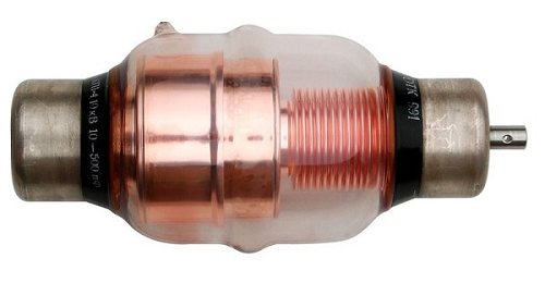
The Vacuum Capacitors uses high vacuum as dielectric instead of air or some other material. These are also available in fixed and variable modes. The construction of these capacitors is similar to vacuum tubes. They are mostly seen in the form of a glass cylinder which contain inter-meshed concentric cylinders.
The following image shows a variable vacuum capacitor.
The following image shows how a fixed vacuum capacitor looks like −
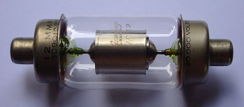
Variable vacuum capacitors are available at a range of 12pF to 5000pF and they are used for high voltage applications such as 5kV to 60kV. They are used in main equipment such as high power broadcast transmitters, RF amplifiers and large antenna tuners.
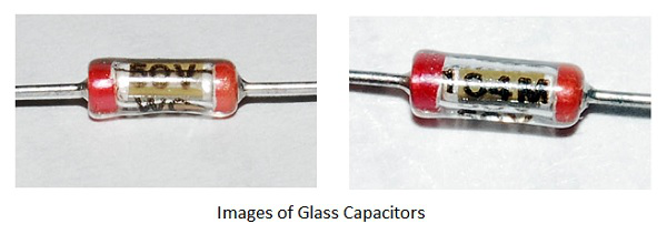
Glass Capacitors
Glass capacitors are very exclusive ones with many advantages and applications. As all of the above types, here glass is the dielectric substance. Along with glass dielectric, Aluminum electrodes are also present in these capacitors. Plastic encapsulation is done after taking out the leads. The leads can be axial leads or tubular leads.
There are many advantages of a glass capacitor such as −
- The temperature coefficient is low.
- These are Noise-free capacitors.
- They produce high quality output with low loss.
- They have the capability of handling high operating temperatures.
- These capacitors can handle large RF currents.
There are many applications for these glass capacitors such as −
- Used in circuits that need to be at high temperature zones.
- Used in circuits that need high Q.
- Used in high power handling circuits.
- Used for circuits that need high tolerances.
Basic Electronics - Polarized Capacitors
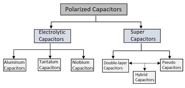
Polarized Capacitors are the ones that have specific positive and negative polarities. While using these capacitors in circuits, it should always be taken care that they are connected in perfect polarities. The following image shows the classification of polarized capacitors.
Let’s start the discussion with Electrolytic Capacitors.
Electrolytic Capacitors
The Electrolytic Capacitors are the capacitors which indicate by the name that some electrolyte is used in it. They are polarized capacitors which have anode (+) and cathode (-) with particular polarities.
A metal on which insulating oxide layer forms by anodizing is called as an Anode. A solid or non-solid electrolyte which covers the surface of the oxide layer, functions as a cathode. The Electrolytic Capacitors have much higher Capacitance-Voltage (CV) value than the others, due to their larger anode surface and thin dielectric oxide layer.
Aluminum Electrolytic Capacitors
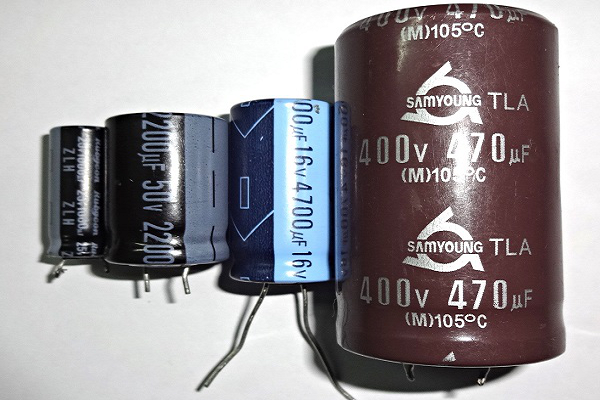
Aluminum Electrolytic Capacitors are the most common types among the Electrolytic capacitors. In these ones, a pure Aluminum foil with an etched surface acts as an Anode. A thin layer of metal, which has a thickness of few micrometers acts as a diffusion barrier, which is placed between two metals to separate electrically. Hence the diffusion barrier acts as a dielectric. The electrolyte acts as a cathode which covers the rough surface of oxide layer.
The following figure shows an image of different sizes of Aluminum Electrolytic Capacitors available.
Depending upon the electrolyte there are three types of Aluminum Electrolytic Capacitors. They are −
- Wet Aluminum Electrolytic capacitors (non-solid)
- Manganese dioxide Aluminum Electrolytic capacitors (solid)
- Polymer Aluminum Electrolytic capacitors (solid)
The main advantage with these Aluminum Electrolytic capacitors is that, they have low impedance values even at mains frequency and they are cheaper. These are mostly used in Power supply circuits, SMPS (Switched Mode Power Supply) and DC-DC Converters.
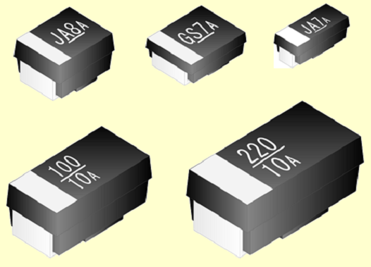
Tantalum Electrolytic capacitors
These are another type of Electrolytic capacitors whose anode is made up of tantalum on which a very thin insulating oxide layer is formed. This layer acts as a dielectric and the electrolyte acts as a cathode which covers the surface of oxide layer.
The following figure shows how tantalum capacitors look like.
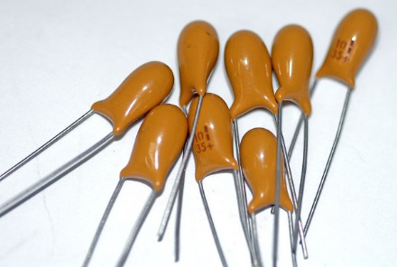
Tantalum provides high permittivity dielectric layer. Tantalum has high capacitance per volume and lower weight. But these ones are costlier than Aluminum Electrolytic capacitors, due to the frequent unavailability of tantalum.
Niobium Electrolytic Capacitors
A Niobium Electrolytic Capacitor is the other type of Electrolytic Capacitors in which a passivated niobium metal or niobium monoxide is considered as anode and an insulating niobium pentoxide layer is added on to the anode, so that it acts as a dielectric. A solid electrolyte is laid on the surface of the oxide layer which acts as a cathode. The following figure shows how Niobium capacitors look like.
The Niobium Capacitors are commonly available as SMD (Surface Mount Devices) chip capacitors. These are easily fitted in a PCB. These capacitors should be operated in perfect polarities. Any kind of reverse voltage or ripple current higher than the specified will eventually destroy the dielectric and the capacitor as well.
Super Capacitors
The high capacity electrochemical capacitors with capacitance values much higher than the other capacitors, are called as Super Capacitors. These can be categorized as a group that lies between electrolytic capacitors and rechargeable batteries. These are also called as Ultra Capacitors.
There are many advantages with these capacitors such as −
- They have high capacitance value.
- They can store and deliver charge much faster.
- They can handle more charge and discharge cycles.
These capacitors have many applications such as −
- They are used in cars, buses, trains, elevators and cranes.
- They are used in regenerative braking.
- They are used for memory backup.
The types of super capacitors are Double-layered, Pseudo and Hybrid ones.
Double-layered Capacitors
Double-layered capacitors are electrostatic capacitors. The charge deposition is done in these capacitors according to the principle of Double-layer.
- All solid substances have negative charge on the surface layer when disposed into a liquid.
- This is due to the high dielectric coefficient of liquid.
- All the positive ions come near the surface of the solid material to make a skin.
- The deposition of positive ions near the solid material get looser with the distance.
- The charge created at this surface due to the deposition of anions and cations leads to some capacitance value.
This double-layer phenomenon is also termed as Helmholtz double layer. The figure below explains the procedure of double-layer phenomenon, when the capacitor is charged and when it is discharged.
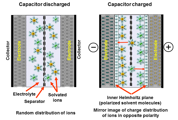
These capacitors are simply called as Electric Double Layered Capacitors (EDLC). They use carbon electrodes to achieve separation of charge between the surface of conductive electrode and the electrolyte. The carbon acts as dielectric and the other two as anode and cathode. The separation of charge is much smaller than in a conventional capacitor.
Pseudo Capacitors
These capacitors follow the electrochemical process for the deposition of charge. This is also called as faradaic process. At an electrode, when some chemical substance reduces or oxidizes, some current is generated. During such process, these capacitors store the electric charge by electron transfer between electrode and electrolyte. This is the working principle of Pseudo capacitors.
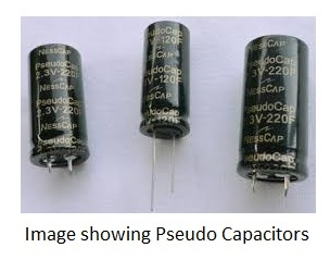
They get charged much faster and store the charge as much as a battery does. They are operated at a faster rate. These are used in tandem with batteries to improve life. These are used in grid applications to handle power fluctuations.
Hybrid Capacitors
A Hybrid Capacitor is a combination of EDLC and Pseudo Capacitor. In the Hybrid capacitors, activated carbon is used as cathode and the pre-doped carbon material acts as anode. Li ion capacitor is the common example of this type. The following figure shows different types of Hybrid Capacitors.
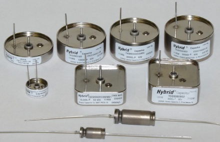
They have high tolerance in a wide range of temperature variations from -55°C to 200°C. Hybrid capacitors are also used in airborne applications. Though cost is high, these capacitors are highly reliable and compact. These are rugged and can tolerate extreme shock, vibration and pressure from environment. Hybrid capacitors have higher energy density and higher specific power than any electrolytic capacitor.
Basic Electronics - Inductors
Let me introduce you to another important component in the field of Electronics and Electricals, the Inductor. Inductor is a passive two-terminal component that temporarily stores energy in the form of a magnetic field. It is usually called as a coil. The main property of an inductor is that it opposes any change in current.
Inductor
According to the Faraday’s law of Electromagnetic induction, When the current flowing through an inductor changes, the time-varying magnetic field induces a voltage in the conductor. According to lens law, the direction of induced EMF opposes the change in current that created it. Hence, induced EMF is opposite to the voltage applied across the coil. This is the property of an inductor.
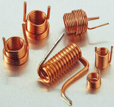
The following figure shows how an inductor looks like.
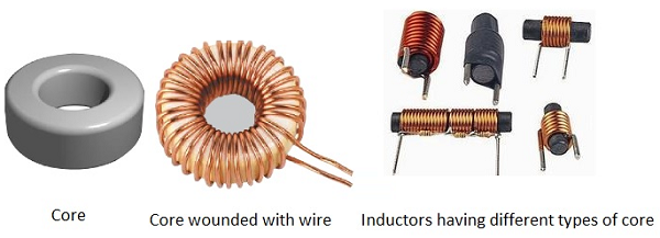
An inductor blocks any AC component present in a DC signal. The inductor is sometimes wrapped upon a core, for example a ferrite core. It then looks as in the figure below.
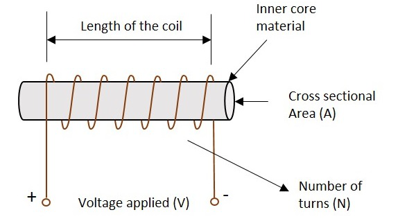
The following figure shows an inductor with various parts labelled.
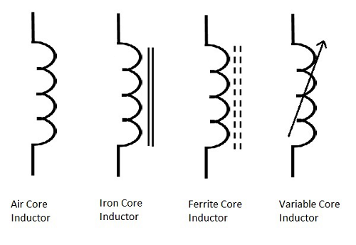
Symbols
The symbols of various types of inductors are as given below.
Storage of Energy
One of the Basic properties of electromagnetism is that the current when flows through an inductor, a magnetic field gets created perpendicular to the current flow. This keeps on building up. It gets stabilized at some point, which means that the inductance won’t build up after that. When the current stops flowing, the magnetic field gets decreased.
This magnetic energy gets turned into electrical energy. Hence energy gets stored in this temporarily in the form of magnetic field.
Working of an Inductor
According to the theory of Electromagnetic Induction, any varying electric current, flowing in a conductor, produces a magnetic field around that, which is perpendicular to the current. Also, any varying magnetic field, produces current in the conductor present in that field, whereas the current is perpendicular to the magnetic field.
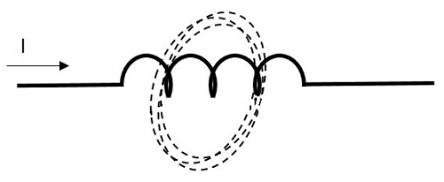
Now, if we consider an inductor which is made up of a conducting coil and when some current passes through the inductor, a magnetic field is created perpendicular to it. The following figure indicates an inductor with magnetic field around it.
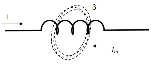
Now, here we have a varying magnetic field, which creates some current through the conductor. But this current is produced such that it opposes the main current, which has produced the magnetic field.
If this current is named as Im which means the current produced due to the magnetic field and the magnetic field is indicated by β, the following figure indicates it.
This opposing current gains strength with the varying magnetic field, which gains energy by the input supply frequency. Hence as the input current becomes more and more AC with high frequency, the resulting opposing current also gains its strength in opposite direction to the very cause producing it. Now, this opposing current, tries to stop the high frequency AC to pass through the inductor, which means “blocking of AC”.
Basic Electronics - Inductance
The property of an inductor to get the voltage induced by the change of current flow, is defined as Inductance. Inductance is the ratio of voltage to the rate of change of current.
The rate of change of current produces change in the magnetic field, which induces an EMF in opposite direction to the voltage source. This property of induction of EMF is called as the Inductance.
The formula for inductance is
Units −
- The unit of Inductance is Henry. It is indicated by L.
- The inductors are mostly available in mH (milli Henry) and μH (micro Henry).
A coil is said to have an inductance of one Henry when an EMF of one volt is self-induced in the coil where the current flowing changed at a rate of one ampere per second.
Self-Inductance
If a coil is considered in which some current flows, it has some magnetic field, perpendicular to the current flow. When this current keeps on varying, the magnetic field also changes and this changing magnetic field, induces an EMF, opposite to the source voltage. This opposing EMF produced is the self-induced voltage and this method is called as self-inductance.
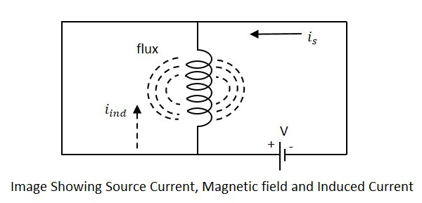
The current is in the figure indicate the source current while iind indicates the induced current. The flux represents the magnetic flux created around the coil. With the application of voltage, the current is flows and flux gets created. When the current is varies, the flux gets varied producing iind.
This induced EMF across the coil is proportional to the rate of change in current. The higher the rate of change in current the higher the value of EMF induced.
We can write the above equation as
Where,
- E is the EMF produced
- dI/dt indicates the rate of change of current
- L indicates the co-efficient of inductance.
Self-inductance or Co-efficient of Self-inductance can be termed as
The actual equation is written as
The minus in the above equation indicates that the EMF is induced in opposite direction to the voltage source according to Lenz’s law.


