


Drift Current
The current formed due to the drift (movement) of charged particles (electrons or holes) due to the applied electric field, is called as Drift Current. The following figure explains the drift current, whether how the applied electric field, makes the difference.
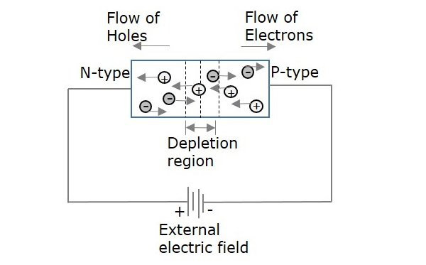
The amount of current flow depends upon the charge applied. The width of depletion region also gets affected, by this drift current. To make a component function in an active circuit, this drift current plays an important role.
Basic Electronics - Resistors
Resist is the word which means “to oppose”. Resistance is the property of opposing the flow of electrons, in a conductor or a semiconductor. A Resistor is an electronic component which has the property of resistance.
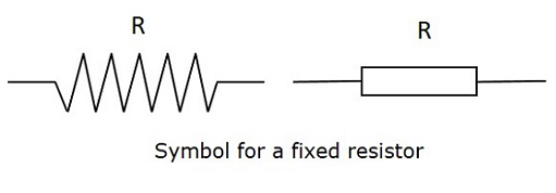
Symbol and Units
The symbol for a Resistor is as shown below.
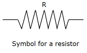
The units of resistance is Ohms, which is indicated by Ω (omega).
The formula for resistance is
R = VI
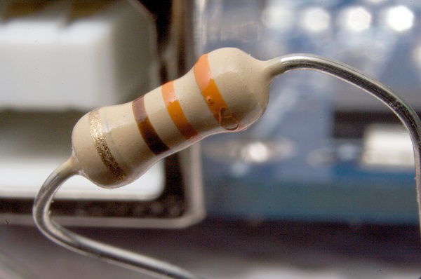
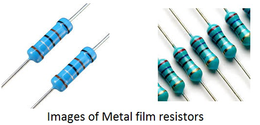
Where V is Voltage and I is Current. It would really be difficult to manufacture the resistors with each and every value. Hence, few values are chosen and the resistors of such values are only manufactured. These are called as “Preferred Values”. In practice, the resistors with near values are chosen to match the required applications. This is how a practical resistor looks like −
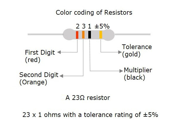
Color Coding
A process called color coding is used to determine the value of resistance for a resistor, just as shown in the above figure. A resistor is coated with four color bands where each color determines a particular value. The below table shows a list of values which each color indicates.
| COLOUR | DIGIT | MULTIPLIER | TOLERANCE |
|---|---|---|---|
| Black | 0 | 100 = 1 | |
| Brown | 1 | 101 = 10 | 1 |
| Red | 2 | 102 = 100 | 2 |
| Orange | 3 | 103 = 1000 | |
| Yellow | 4 | 104 = 10000 | |
| Green | 5 | 105 = 100000 | 0.5 |
| Blue | 6 | 106 = 1000000 | 0.25 |
| Violet | 7 | 107 = 10000000 | 0.1 |
| Gray | 8 | 108 = 100000000 | |
| White | 9 | 109 = 1000000000 | |
| Gold | 10-1 = 0.1 | 5 | |
| Silver | 10-2 = 0.01 | 10 | |
| (none) | 20 |
The first two colored bands indicate the first and second digit of the value and the third color band represents the multiplier (number of zeroes added). The fourth color band indicates the tolerance value.
Tolerance is the range of value up to which a resistor can withstand without getting destroyed. This is an important factor. The following figure shows how the value of a resistor is determined by color code.
The five color band resistors are manufactured with tolerance of 2% and 1% and also for other high accuracy resistors. In these five band resistors, the first three bands represent digits, fourth one indicates multiplier and the fifth represents tolerance.
Let us look at an example to understand the color coding process.
Example 1 − Determine the value of a resistor with a color code yellow, blue, orange and silver.
Solution − The value of yellow is 4, blue is 6, orange is 3 which represents multiplier. Silver is ±10 which is the tolerance value.
Hence the value of the resistor is 46×103 = 46kΩ
The maximum resistance value for this resistor is
46kΩ or 46000Ω + 10% = 46000 + 4600 = 50600Ω = 50.6kΩ
The minimum resistance value for this resistor is
46kΩ or 46000Ω - 10% = 46000 - 4600 = 41400Ω = 41.4kΩ
After having gone through different details regarding resistors, we have some terms to learn. Also we have to deal with different behaviors of a resistor for few types of connections.
Important Terms
There are a few terms which we need to discuss before going into the type of resistors we have. One needs to get introduced to these terms at this stage and can understand them as we progress further.
Resistance
Resistance is the property of a resistor that opposes the flow of current. When alternating current goes through a resistance, a voltage drop is produced that is in-phase with the current.
- Indication − R
- Units − Ohms
- Symbol − Ω
Along with resistance, there are other important terms, called as reactance and impedance.
Reactance
The resistance offered to the alternating current because of the capacitances and inductances present in the circuit, can be understood as reactance. When alternating current goes through a pure reactance, a voltage drop is produced that is 90°out of phase with the current.
Depending upon the phase i.e., +90° or -90° the reactance can be termed as inductive reactance or capacitive reactance.
- Indication − X
- Units − Ohms
- Symbol − Ω
Impedance
Impedance is the effective resistance to alternating current arising from the combined effects of ohmic resistance and reactance. When alternating current goes through an impedance, a voltage drop is produced which is somewhere between 0°to 90°out of phase with the current.
- Indication − I
- Units − Ohms
- Symbol − Ω
Conductance
This is the ability of a material to conduct electricity. It is the reciprocal of resistance.
- Indication − G
- Units − Mhos
- Symbol − ℧
Circuit Connections in Resistors
A Resistor when connected in a circuit, that connection can be either series or parallel. Let us now know what will happen to the total current, voltage and resistance values if they are connected in series as well, when connected in parallel.
Resistors in Series
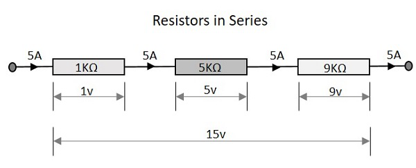
Let us observe what happens, when few resistors are connected in Series. Let us consider three resistors with different values, as shown in the figure below.
Resistance
The total resistance of a circuit having series resistors is equal to the sum of the individual resistances. That means, in the above figure there are three resistors having the values 1KΩ, 5KΩ and 9KΩ respectively.
Total resistance value of the resistor network is −
Which means 1 + 5 + 9 = 15KΩ is the total resistance.
Where R1 is the resistance of 1st resistor, R2 is the resistance of 2nd resistor and R3 is the resistance of 3rd resistor in the above resistor network.
Voltage
The total voltage that appears across a series resistors network is the addition of voltage drops at each individual resistances. In the above figure we have three different resistors which have three different values of voltage drops at each stage.
Total voltage that appears across the circuit −
Which means 1v + 5v + 9v = 15v is the total voltage.
Where V1 is the voltage drop of 1st resistor, V2 is the voltage drop of 2ndresistor and V3 is the voltage drop of 3rd resistor in the above resistor network.
Current
The total amount of Current that flows through a set of resistors connected in series is the same at all the points throughout the resistor network. Hence the current is same 5A when measured at the input or at any point between the resistors or even at the output.
Current through the network −
Which means that current at all points is 5A.
Where I1 is the current through the 1st resistor, I2 is the current through the 2nd resistor and I3 is the current through the 3rd resistor in the above resistor network.
Resistors in Parallel
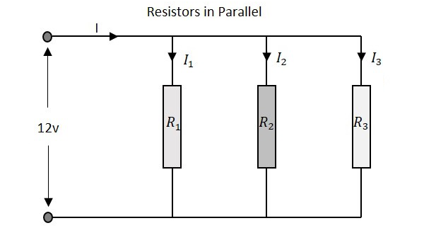
Let us observe what happens, when few resistors are connected in Parallel. Let us consider three resistors with different values, as shown in the figure below.
Resistance
The total resistance of a circuit having Parallel resistors is calculated differently from the series resistor network method. Here, the reciprocal (1/R) value of individual resistances are added with the inverse of algebraic sum to get the total resistance value.
Total resistance value of the resistor network is −
Where R1 is the resistance of 1st resistor, R2 is the resistance of 2nd resistor and R3 is the resistance of 3rd resistor in the above resistor network.
For example, if the resistance values of previous example are considered, which means R1 = 1KΩ, R2 = 5KΩ and R3 = 9KΩ. The total resistance of parallel resistor network will be −
From the method we have for calculating parallel resistance, we can derive a simple equation for two-resistor parallel network. It is −
Voltage
The total voltage that appears across a Parallel resistors network is same as the voltage drops at each individual resistance.
The Voltage that appears across the circuit −
Where V1 is the voltage drop of 1st resistor, V2 is the voltage drop of 2ndresistor and V3 is the voltage drop of 3rd resistor in the above resistor network. Hence the voltage is same at all the points of a parallel resistor network.
Current
The total amount of current entering a Parallel resistive network is the sum of all individual currents flowing in all the Parallel branches. The resistance value of each branch determines the value of current that flows through it. The total current through the network is
Where I1 is the current through the 1st resistor, I2 is the current through the 2nd resistor and I3 is the current through the 3rd resistor in the above resistor network. Hence the sum of individual currents in different branches obtain the total current in a parallel resistive network.
A Resistor is particularly used as a load in the output of many circuits. If at all the resistive load is not used, a resistor is placed before a load. Resistor is usually a basic component in any circuit.
Basic Electronics - Non linear Resistors
There are many types of resistors according to the type of material used, the manufacturing procedure and their applications. The classification is as shown below.
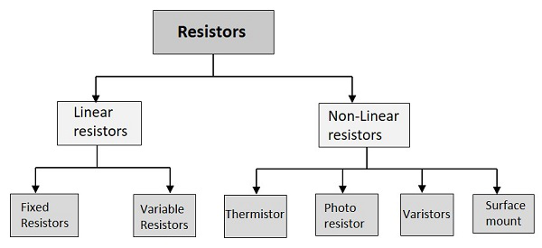
Linear resistors have linear VI characteristics and non-linear resistors has non-linear VI characteristics. Non-linear resistors are the resistors whose voltage and current characteristics vary non-linearly. The voltage and current values vary depending upon other factors like temperature and light, but they may not be linear.
Thermistor
Thermal means temperature. In this resistor, the resistance varies with temperature. If heat increases, the resistance decreases and vice versa. This is used for measurement and control purposes.
The main types of thermistors are NTC and PTC.
- NTC is Negative Temperature Coefficient and in such devices, the resistance decreases as the temperature increases. These are used to protect the devices from over-voltage conditions.
- PTC is Positive Temperature Coefficient and in such devices, the resistance increases as the temperature increases. These are used to protect the devices from over current conditions.
The following figure shows an NTC thermistor, along with its symbol.
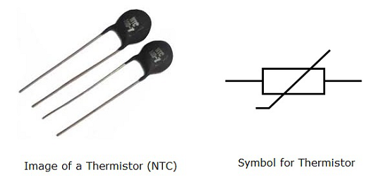
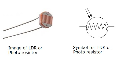
Photo Resistor
Photo means light. In this resistor, the resistance varies with light. As light increases resistance decreases and vice versa. This is also used for measurement and control purposes. It is also called as LDR (Light Dependent Resistor)
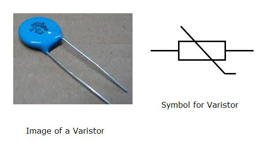
Varistors
The resistance of a varistor, varies with the applied voltage. As the voltage increases, the resistance decreases and if the voltage decreases, the resistance increases. It is also called as VDR (Voltage Dependent Resistor).
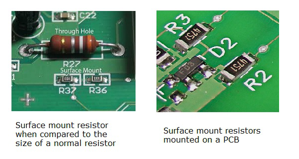
Surface Mount
These are being highly used since the introduction of surface mount technology. These can be termed as chip resistors, which means a resistive layer integrated on a ceramic chip.
These surface mount resistors are very small when compared to the normal resistors and hence occupy less space. They are effective and dissipate less heat. The invention of these resistors has changed the look of a PCB (Printed Circuit Board) and reduced its size greatly.
The advantages of surface mount resistors are −
- These are compact in size.
- These are very stable.
- They have good tolerance.
- They are effective in reducing heat dissipation.
The following figure shows the images of surface mount resistors.
Basic Electronics - Linear Resistors
A Linear resistor is one whose resistance doesn’t vary with the flow of current through it. The current through it, will always be proportional to the voltage applied across it. Linear resistors are further classified as Fixed and Variable resistors.
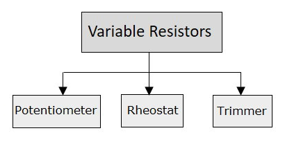
Variable Resistors
Variable resistors are those whose values can be varied manually, according to the requirement. A particular value of resistance is chosen from a range of resistance values, with the help of a shaft connected. The symbol of a variable resistor is as shown below.
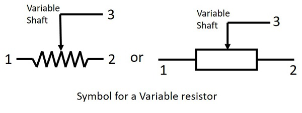
These resistors are better understood with the help of the classification we have. Variable resistors are further divided into Potentiometers, Rheostats and Trimmers.
Potentiometer
A Potentiometer is simply called as a Pot. This is a three-terminal resistor having a shaft which slides or rotates. This shaft when operated forms an adjustable voltage divider. The following figure shows an image of a Potentiometer.
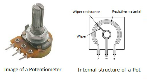
A potentiometer also measures the potential difference (voltage) in a circuit. A path of resistive material with resistance of low to high value is laid internally and a wiper is placed so that it connects the resistive material to the circuit. This is mostly used as a volume controller in TV sets and Music systems.
Rheostat
A Rheostat can be simply called as a Wire wound resistor. A Resistive wire is wound around an insulating ceramic core tightly. A Wiper slides over these windings. One connection is made to one end of the resistive wire and the second connection is made to the wiper or the sliding contact, to obtain the desired resistance.
The Rheostat is used to control current. These are mostly used in the speed control of heavy motors. The resistance obtained by these is in the order of kilo ohms. Rheostats are mostly available as single tube and double tube rheostats, as shown in the following figure.
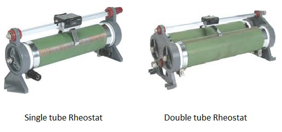
As a variable resistance they are often used for tuning and calibration in circuits. Now-a-days, the usage of rheostats was replaced by switching electronic devices, as rheostats have lower efficiency.
Trimmer
Trimmer is both a variable resistor and a potentiometer (measures potential difference). This Trimmer Potentiometer is, in short called as Trim Pot. If these are used as variable resistors, then they are called as Preset Resistors.
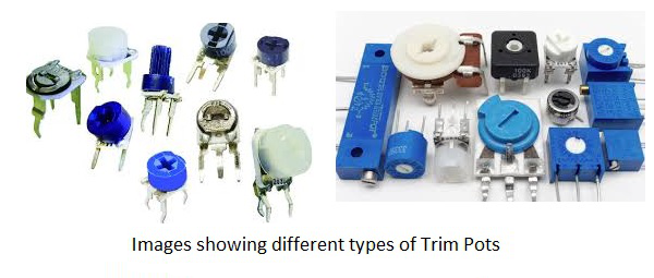
These trim pots are of different types such as single turn or multi turn. These are small variable resistors used for tuning and calibration. Their life span is shorter than other variable resistors.
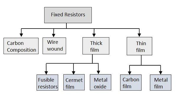
Basic Electronics - Fixed Resistors
Fixed resistors are one type of linear resistors. A resistor is said to be a fixed resistor, if its value is fixed. The value of fixed resistor can’t be varied like a variable resistor as its value is determined at the time of manufacturing itself. The following figures represent the symbol of a fixed resistor.
The fixed resistors are classified into different types, depending upon their manufacturing processes and the materials used in their manufacturing. The classification is as follows.
Carbon composition
The Carbon composition resistors are a blend of carbon particles, graphite and ceramic dust mixed with a binder substance like clay. This mixture is treated with high pressure and temperature. After the whole thing is molded in a case, the leads are fixed.
- Thermal mass of the carbon composition resistor is higher so as to withstand high energy pulses.
- These resistors have low stability and high noise which is a disadvantage.
The following figure shows an image of carbon composition resistor.
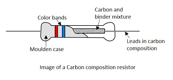
Carbon composition resistors are used in Surge protection, Current limiting, and High voltage power supplies.
Wire wound
A Wire wound resistor is formed by wounding a wire made up of a resistive material around a core. The metallic core acts as a non-conductive material while the resistive wire conducts, but with some resistance. The image of a wire wound resistor is as shown below.
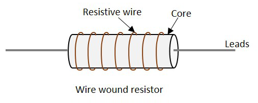
Usually a nichrome wire or a manganin wire is used to wind the core because they offer high resistance. Whereas plastic, ceramic or glass is used for core.
- Wire wound resistors are very accurate.
- They work excellently for low resistance values and high power ratings.
These are the oldest type of fixed resistors, but are being used even now.
Thick Film
The film resistors have a resistive layer on a ceramic base, whose thickness defines the type they belong to. The thickness of resistive layer on thick film resistors is much higher than thin film resistors. Thick film resistors are produced by firing a special paste, which is a mixture of glass and metal oxides, onto the substrate.
There are three main types in thick film resistors like Fusible resistors, Cermet film resistors, and Metal oxide film resistors.
Fusible Resistors
The Fusible resistors are similar to wire wound resistors. But these resistors along with providing resistance, act as a fuse. The image of a fusible resistor is as shown below.
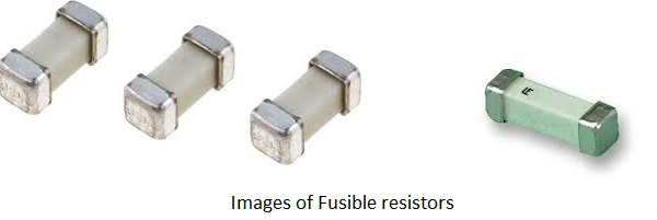
In this resistor, the current flows through a spring loaded connection, which is placed closely to the body of the resistor. The blob that is attached to the spring wire of the resistor takes the heat generated by the resistor due to the current flow. If this heat is increased, the attachment to the blob gets melted up and opens the connection.

Hence we can say that, these resistors limit the current, but if the circuit power rating exceeds a specified value, these resistors act as a fuse to open or break the circuit. The value of these resistors is usually of less than 10 Ohms. These resistors are generally used in TV sets, amplifiers and other expensive electronic circuits.
Cermet Film Resistors
The Cermet film resistors are the film resistors made up of a special material called Cermet. Cermet is a composite alloy made by combining Ceramic and Metal. This combination provides the advantages in both of these materials like high temperature resistance and wear resistance of ceramic along with flexibility and electrical conductivity of a metal.
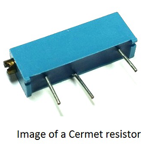
A metal film layer is wrapped around a resistive material and is fixed in a ceramic metal or cermet substrate. Leads are taken to make the connections easy while fixing on a PCB. They offer high stability as temperature cannot affect their performance.
Metal Oxide film resistors
A Metal oxide film resistor is formed by oxidizing a thick film of Tin chloride on a heated glass rod, which is a substrate. They have high temperature stability and can be used at high voltages. These resistors have low operating noise.
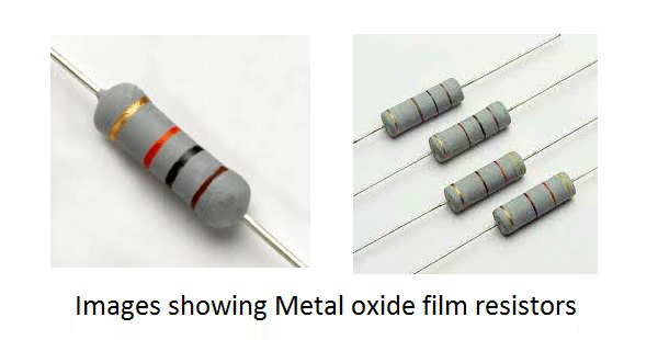
Metal oxide film resistors differ with metal film ones only regarding the type of film coated. Metal oxide is a metallic compound like tin with oxygen to form tin oxide, which is coated as a film on the resistor. The resistivity of this resistor depends upon the amount of antimony oxide added to the tin oxide.
Thin Film
Thin film resistors have a resistive layer of width 0.1 micrometer or smaller on the ceramic base. Thin film resistors have a metallic film that is vacuum deposited on an insulating substrate.
Thin film resistors are more accurate and have better temperature coefficient and is more stable. The thin film resistors are further divided into two types such as −
- Carbon film resistors
- Metal film resistors
Carbon film resistor
A Carbon film resistor is made by depositing a carbon film layer on a ceramic substrate. The carbon film acts as the resistive material to the current and the ceramic substance acts as an insulating substance. Metallic caps are fixed at both the ends and copper leads are drawn out.
The following figure shows the construction of a carbon film resistor.
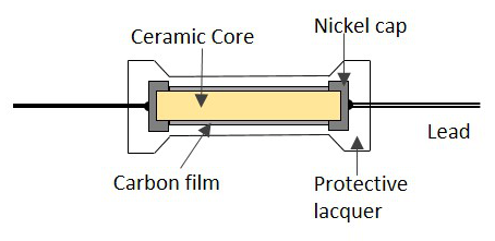
The main advantages of these resistors are their high stability, wide operating range, low noise, and low cost. The carbon film resistors are the most preferred ones over carbon composition resistors due to their low noise.
Metal Film Resistors
The film coating makes the difference between metal oxide film resistors and metal film resistors. A thin film of metallic substance such as nickel chromium is used to coat the resistor in a metal film resistor whereas a film of metal oxide like tin oxide is used to coat the resistor in a metal oxide resistor.
Metal film resistors have low temperature coefficient of resistance, which means the resistance is less affected by the temperature.
Wattage
While using a resistor, if the flow of current increases, the resistor dissipates some heat. If this value crosses a certain critical value, the resistor may get damaged. The wattage rating of a resistor is printed on some higher value resistors in order to avoid such situation.
Wattage is the amount of electric power expressed in watts. Electric power is the rate of transfer of electrical energy.
Power P = VI = I2R
Basic Electronics - Capacitors
A Capacitor is a passive component that has the ability to store the energy in the form of potential difference between its plates. It resists a sudden change in voltage. The charge is stored in the form of potential difference between two plates, which form to be positive and negative depending upon the direction of charge storage.
A non-conducting region is present between these two plates which is called as dielectric. This dielectric can be vacuum, air, mica, paper, ceramic, aluminum etc. The name of the capacitor is given by the dielectric used.
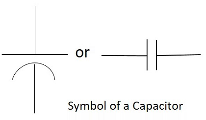
Symbol and Units
The standard units for capacitance is Farads. Generally, the values of capacitors available will be in the order of micro-farads, pico-farads and nano-farads. The symbol of a capacitor is as shown below.
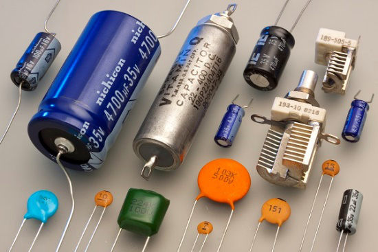
The Capacitance of a capacitor is proportional to the distance between the plates and is inversely proportional to the area of the plates. Also, the higher the permittivity of a material, the higher will be the capacitance. The permittivity of a medium describes how much electric flux is being generated per unit charge in that medium. The following image shows some practical capacitors.
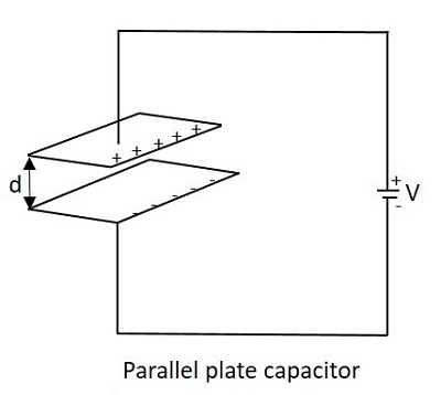
When two plates having same area A, and equal width are placed parallel to each other with a separation of distance d, and if some energy is applied to the plates, then the capacitance of that parallel plate capacitor can be termed as −
Where
C = Capacitance of a capacitor
= permittivity of free space
= permittivity of dielectric medium
d = distance between the plates
A = area of the two conducting plates
With some voltage applied, the charge deposits on the two parallel plates of the capacitor. This charge deposition occurs slowly and when the voltage across the capacitor equals the voltage applied, the charging stops, as the voltage entering equals the voltage leaving.
The rate of charging depends upon the value of capacitance. The greater the value of capacitance, the slower the rate of change of voltage in the plates.
Working of a Capacitor
A Capacitor can be understood as a two-terminal passive component which stores electrical energy. This electrical energy is stored in electrostatic field.
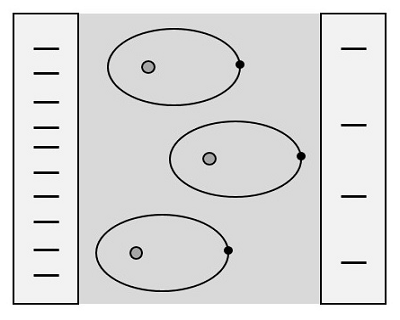
Initially, the negative and positive charges on two plates of the capacitor are in equilibrium. There is no tendency for a capacitor to get charged or discharged. The negative charge is formed by the accumulation of electrons, while the positive charge is formed by the depletion of electrons. As this happens without any external charge given, this state is electrostatic condition. The figure below shows the capacitor with static charges.
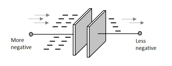
The accumulation and depletion of electrons according to the varying positive and negative cycles of the AC supply, can be understood as “current flow”. This is called as Displacement Current. The direction of this current flow keeps on changing as this is AC.
Charging of a Capacitor
When an external voltage is given, the electric charge gets converted into electrostatic charge. This happens while the capacitor is charging. The positive potential of the supply, attracts the electrons from the positive plate of the capacitor, making it more positive. While the negative potential of the supply, forces the electrons to the negative plate of the capacitor, making it more negative. The figure below explains this.
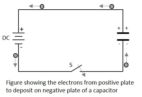
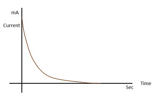
During this process of charging, the electrons move through the DC supply but not through the dielectric which is an insulator. This displacement is large, when the capacitor starts to charge but reduces as it charges. The capacitor stops charging when the voltage across capacitor equals the supply voltage.
Let us see what happens to the dielectric when the capacitor begins to charge.
Dielectric behavior
As the charges deposit on the plates of the capacitor, an electrostatic field is formed. The strength of this electrostatic field depends upon the magnitude of charge on the plate and the permittivity of the dielectric material. Permittivity is the measure of dielectric whether how far it allows the electrostatic lines to pass through it.
The dielectric is actually an insulator. It has electrons in the outer most orbit of the atoms. Let us observe how they get affected. When there is no charge on the plates, the electrons in the dielectric move in circular orbit. This is as shown in the figure below.
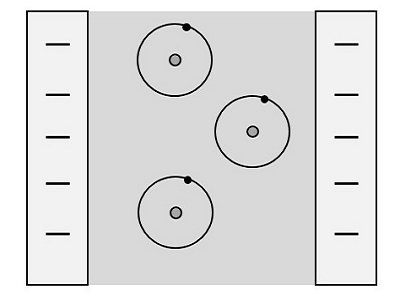
When charge deposition takes place, the electrons tend to move towards the positive charged plate, but still they keep on revolving as shown in the figure.
If the charge increases further, the orbits expand more. But if it still increases, the dielectric breaks down shorting the capacitor. Now, the capacitor being fully charged, it’s ready to get discharged. It is enough if we provide a path for them to travel from negative to positive plate. The electrons flow without any external supply as there are too many number of electrons on one side and barely any electrons on the other. This imbalance is adjusted by the discharge of the capacitor.
Also, when a discharge path is found, the atoms in the dielectric material tend to get to their normal circular orbit and hence forces the electrons to get discharged. This kind of discharge enables capacitors to deliver high currents in a short period of time, just as in a camera flash.
Color Coding
To know the value of a capacitor, it is usually labelled as below −
n35 = 0.35nF or 3n5 = 3.5nF or 35n = 35nF and so on.
Sometimes the markings will be like 100K which means, k = 1000pF. Then the value will be 100 × 1000pF = 100nF.
Though these number markings are being used now-a-days, an International color coding scheme was developed long ago, to understand the values of capacitors. The color coding indications are just as given below.
| Band colour | Digit A and B | Multiplier | Tolerance (t) > 10pf | Tolerance (t) < 10pf | Temperature coefficient |
|---|---|---|---|---|---|
| Black | 0 | × 1 | ±20% | ±2.0pF | |
| Brown | 1 | × 10 | ±1% | ±0.1pF | -33 × 10-6 |
| Red | 2 | × 100 | ±2% | ±0.25pF | -75 × 10-6 |
| Orange | 3 | × 1,000 | ±3% | -150 × 10-6 | |
| Yellow | 4 | × 10,000 | ±4% | -220 × 10-6 | |
| Green | 5 | × 100,000 | ±5% | ±0.5pF | -330 × 10-6 |
| Blue | 6 | × 1,000000 | -470 × 10-6 | ||
| Violet | 7 | -750 × 10-6 | |||
| Gray | 8 | × 0.01 | +80%, -20% | ||
| White | 9 | × 0.1 | ±10% | ±1.0pF | |
| Gold | × 0.1 | ±5% | |||
| Silver | × 0.01 | ±10% |
These indications were used to identify the value of capacitors.
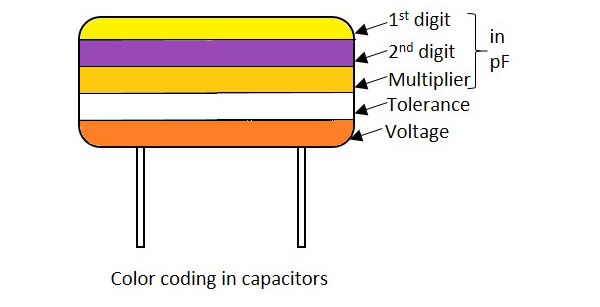
In these five band capacitors, the first two bands represent digits, third one indicates multiplier, fourth for tolerance and the fifth represents voltage. Let us look at an example to understand the color coding process.
Example 1 − Determine the value of a capacitor with a color code yellow, violet, orange, white and red.
Solution − The value of yellow is 4, violet is 7, orange is 3 which represents multiplier. White is ±10 which is the tolerance value. Red represents the voltage. But to know the voltage rating, we have got another table, from which the particular band to which this capacitor belongs, has to be known.
Hence the value of the capacitor is 47nF, 10% 250v (voltage for V band)
The following table shows how voltage is determined depending upon the bands the capacitors belong to.
| Band colour | Voltage Rating (V) | ||||
|---|---|---|---|---|---|
| TYPE J | TYPE K | TYPE L | TYPE M | TYPE N | |
| Black | 4 | 100 | 10 | 10 | |
| Brown | 6 | 200 | 100 | 1.6 | |
| Red | 10 | 300 | 250 | 4 | 35 |
| Orange | 15 | 400 | 40 | ||
| Yellow | 20 | 500 | 400 | 6.3 | 6 |
| Green | 25 | 600 | 16 | 15 | |
| Blue | 35 | 700 | 630 | 20 | |
| Violet | 50 | 800 | |||
| Gray | 900 | 25 | 25 | ||
| White | 3 | 1000 | 2.5 | 3 | |
| Gold | 2000 | ||||
| Silver | |||||
With the help of this table, the voltage rating for each band of capacitors is known according to the color given. The type of voltage ratings also indicates the type of capacitors. For example, TYPE J ones are Dipped Tantalum Capacitors, TYPE K ones are Mica Capacitors, TYPE L ones are Polystyrene Capacitors, TYPE M ones are Electrolytic Band 4 Capacitors and TYPE N ones are Electrolytic Band 3 Capacitors. These days, the color coding has been replaced by simple printing of value of the capacitors as mentioned previously.
Capacitive Reactance
This is an important term. Capacitive Reactance is the opposition offered by a capacitor to the alternating current flow, or simply AC current. A capacitor resists the change in the flow of current and hence it shows some opposition which can be termed as reactance, as the frequency of the input current should also be considered along with the resistance it offers.
Symbol: XC
In a purely capacitive circuit, the current IC leads the applied voltage by 90°
Temperature Coefficient of Capacitors
The maximum change in Capacitance of a capacitor, over a specified temperature range, can be known by the temperature coefficient of a capacitor. It states that when the temperature exceeds a certain point, the change in capacitance of a capacitor that might occur is understood as the temperature coefficient of capacitors.
All the capacitors are usually manufactured considering a reference temperature of 25°C. Hence the temperature coefficient of capacitors is considered for the values of temperatures that are above and below this value.
Circuit Connections in Capacitors
In a circuit, a Capacitor can be connected in series or in parallel fashion. If a set of capacitors were connected in a circuit, the type of capacitor connection deals with the voltage and current values in that network.
Capacitors in Series
Let us observe what happens, when few Capacitors are connected in Series. Let us consider three capacitors with different values, as shown in the figure below.
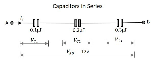
Capacitance
When the capacitance of a network whose capacitors are in series is considered, the reciprocal of the capacitances of all capacitors, is added to get the reciprocal of the total capacitance. To get this more clearly,
Following the same formula, if simply two capacitors are connected in series, then
Where C1 is the capacitance across the 1st capacitor, C2 is the capacitance across the 2nd capacitor and C3 is the capacitance across the 3rd capacitor in the above network.
Voltage
The voltage across each capacitor depends upon the value of individual capacitances. Which means
The total voltage across the series capacitors circuit,
Where Vc1 is the voltage across the 1st capacitor, Vc2 is the voltage across the 2nd capacitor and Vc3 is the voltage across the 3rd capacitor in the above network.
Current
The total amount of Current that flows through a set of Capacitors connected in series is the same at all the points. Therefore the capacitors will store the same amount of charge regardless of their capacitance value.
Current through the network,
Where I1 is the current through the 1st capacitor, I2 is the current through the 2nd capacitor and I3 is the current through the 3rd capacitor in the above network.
As the current is same, the storage of charge is same because any plate of a capacitor gets its charge from the adjacent capacitor and hence capacitors in series will have the same charge.
Capacitors in Parallel
Let us observe what happens, when few capacitors are connected in Parallel. Let us consider three capacitors with different values, as shown in the figure below.
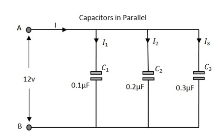
Capacitance
The total Capacitance of the circuit is the equivalent to the sum of the individual capacitances of the capacitors in the network.
Where C1 is the capacitance across the 1st capacitor, C2 is the capacitance across the 2nd capacitor and C3 is the capacitance across the 3rd capacitor in the above network.
Voltage
The voltage measured at the end of the circuit is same as the voltage across all the capacitors that are connected in a parallel circuit.
Where Vc1 is the voltage across the 1st capacitor, Vc2 is the voltage across the 2nd capacitor and Vc3 is the voltage across the 3rd capacitor in the above network.
Current
The total current flowing is equal to the sum of the currents flowing through each capacitor connected in the parallel network.
Where I1 is the current through the 1st capacitor, I2 is the current through the 2nd capacitor and I3 is the current through the 3rd capacitor in the above network.
Basic Electronics - Variable Capacitors
There are many types of capacitors depending upon their function, the dielectric material used, their shape etc. The main classification is done according to fixed and variable capacitors.
Types of Capacitors
The classification is as shown in the following figure.
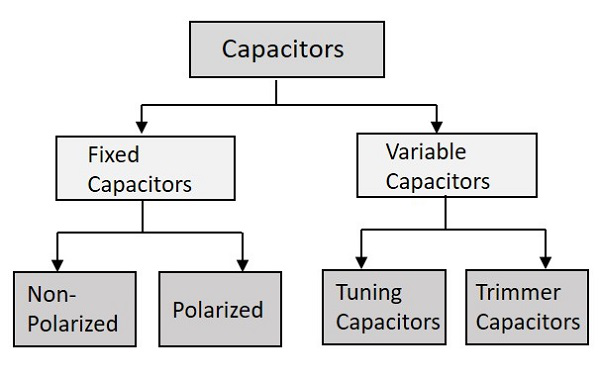
The main classification is just like the above one. The fixed capacitors are the ones whose value is fixed at the time of manufacturing itself and the variable ones provide us with an option to vary the value of capacitance.
Variable Capacitors
Let us know something about the variable capacitors whose value alters when you vary, either electrically or mechanically. Variable capacitors in general consists of interwoven sets of metallic plates in which one is fixed and the other is variable. These capacitors provide the capacitance values so as to vary between 10 to 500pF.
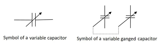
The ganged capacitor shown here is a combination of two capacitors connected together. A single shaft is used to rotate the variable ends of these capacitors which are combined as one. The dotted line indicates that they are connected internally.
There are many uses of these variable resistors such as for tuning in LC circuits of radio receivers, for impedance matching in antennas etc. The main types of variable capacitors are Tuning capacitors and Trimmer capacitors.
Tuning Capacitors
Tuning capacitors are popular type of variable capacitors. They contain a stator, a rotor, a frame to support the stator and a mica capacitor. The constructional details of a tuning capacitor are shown in the following figure.
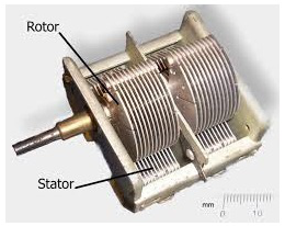
The stator is a stationary part and rotor rotates by the movement of a movable shaft. The rotor plates when moved into the slots of stator, they come close to form plates of a capacitor. When the rotor plates sit completely in the slots of the stator then the capacitance value is maximum and when they don’t, the capacitance value is minimum.
The above figure shows a ganged tuning capacitor having two tuning capacitors connected in a gang. This is how a tuning capacitor works. These capacitors generally have capacitance values from few Pico Farads to few tens of Pico Farads. These are mostly used in LC circuits in radio receivers. These are also called as Tuning Condensers.
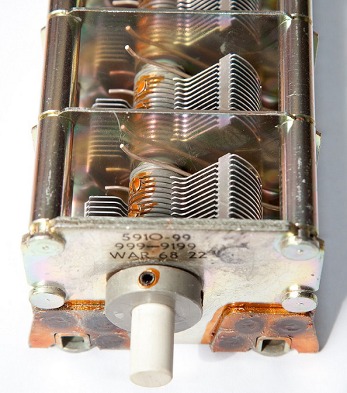
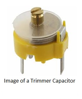
Trimmer Capacitors
Trimmer capacitors are varied using a screwdriver. Trimmer capacitors are usually fixed in such a place where there is no need to change the value of capacitance, once fixed.
There are three leads of a trimmer capacitor, one connected to stationary plate, one to rotary and the other one is common. The movable disc is a semi-circular shaped one. A trimmer capacitor would look like the ones in the following figure.
There are two parallel conducting plates present with a dielectric in the middle. Depending upon this dielectric used, there are air trimmer capacitors and ceramic trimmer capacitors. The constructional details of a trimmer capacitor are as shown below.
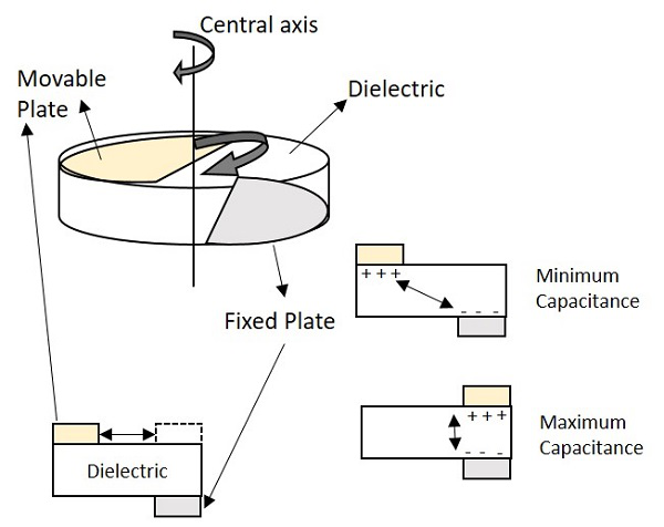
One of the two plates is movable, while the other is fixed. The dielectric material is fixed. When the movable plate is moved, opposite to the area between movable and fixed electrode, then the capacitance can be changed. The capacitance will be higher if the opposite area gets bigger, as both the electrodes act as two plates of a capacitor.
The Trimmer Capacitors are easily fixed on a PCB (Printed Circuit Board) and they are mostly used for calibration of equipment.


